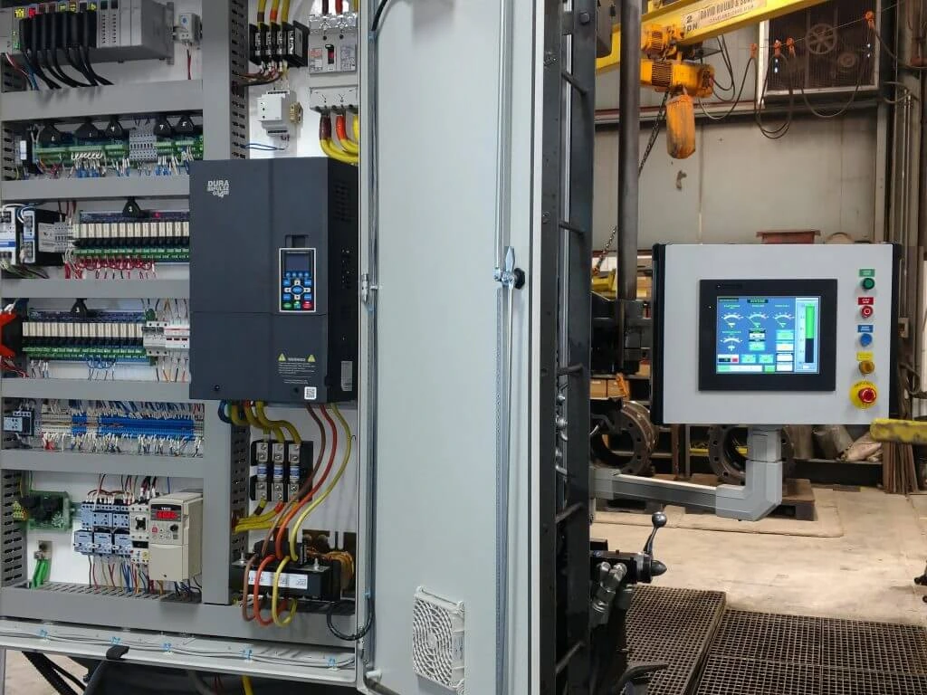
EMAN FTC / Water pump VFD guide
A booster pump can start perfectly and still deliver the wrong pressure. The real test is how the system responds when water demand changes.
Installing and configuring a VFD control panel for water pumps involves matching the drive to the motor, setting up pressure feedback, and testing the pump under the conditions it will face on site. Follow this guide from panel selection through commissioning and handover.
How Does a VFD Control Panel Work for a Water Pump?
Quick answer
A variable frequency drive (VFD) adjusts the speed of a compatible pump motor. In a constant-pressure system, the drive or PLC compares the measured pressure with a setpoint and adjusts pump speed as water demand changes.
The VFD is one component inside the panel. The complete assembly may also include protective devices, terminals, an operator interface, and a Hand–Off–Auto selector. The panel design determines how those parts interact with the pump, the pressure transmitter, and the rest of the facility.
A factory booster pump may maintain discharge pressure as more outlets open. A transfer pump might respond to a tank level, while a hospital chilled-water pump might respond to a differential pressure measurement. Each application starts with the process variable the system needs to control. Explore the types of electrical and automation control panels.
What to Check Before Installing a Water Pump VFD Panel
Start with the motor nameplate and the pump duty, meaning the flow and head the pump must deliver. Two motors with the same kilowatt rating can have different rated currents or operating requirements. The selected drive must suit the motor, the available supply, and the expected load duty.
- Motor and supply. Record the motor type, rated voltage, current, frequency, speed, and power. Confirm the site supply and protection requirements.
- Pump and pipework. Collect the pump curve, required flow and head, normal and peak demand, and the manufacturer’s operating limits. Note any minimum-flow requirements.
- Controls and instruments. Identify the transmitter’s output signal and range, the source of start commands, and any alarms or feedback required by the PLC or building management system.
- Installation environment. Check the temperature inside the enclosure, dust exposure, cooling, cable entry, and space for maintenance. Confirm manufacturer derating where applicable, especially for outdoor or uncooled installations.
Give suppliers the same information when requesting quotes. This makes it easier to compare the proposed drive, enclosure, controls, and commissioning scope on the same basis. See Grundfos guidance on the pump operating curve.
Pump and drive products from EMAN FTC
EMAN FTC lists industrial drives and water pumps separately. Use these product enquiries to start the discussion, then confirm the exact pump, motor, and drive configuration against the project requirements.
- Request ABB ACS880 industrial drive details
- Request Danfoss VLT AutomationDrive details
- Request Grundfos CM Series multistage pump details
- Request VERDONOW industrial booster pump system details
Browse VFDs and automation products · Browse water pumps and booster systems
How to Install a VFD Control Panel for a Water Pump
Qualified electrical personnel should install the panel using the approved drawings, site isolation procedure, and installation manual for the exact drive. The panel drawings establish how the supply, motor, protective earth, and control signals connect.
- Confirm the mounting location. Verify enclosure clearances, cooling airflow, cable access, and space to open doors and service the equipment.
- Check the power and control routes. Review cable separation, earthing, and shielding against the approved drawings and manufacturer’s instructions. Pay particular attention to the pressure transmitter cable, since reliable feedback matters for pressure control.
- Complete the pre-start inspection. Confirm equipment identification, protective devices, terminations, and the pump’s mechanical readiness before authorised startup. Record any outstanding items and close them before proceeding.
Use the exact model’s documentation for terminal assignments, discharge times, and electrical verification. See the Schneider Electric ATV630 and ATV650 installation manual.
How to Configure the VFD for the Pump Motor
Start by recording three groups of settings. The motor nameplate supplies the rated voltage, current, frequency, speed, and power. The pump and system design supplies the approved speed range and acceleration and deceleration requirements. The control sequence determines where start and stop commands and the speed reference come from.
These last two signals do different jobs. A local selector can give permission to run in Hand mode while an operator selects the speed. In Auto, the drive’s PID controller may adjust speed from pressure feedback, or a PLC may run the loop and send a speed reference. Record which device has control in each mode so the operator can tell why the pump starts and what sets its speed.
Confirm motor rotation using the approved startup procedure. Once the configuration is accepted, record the drive model and firmware version with the final settings. These details make a parameter backup more useful during future maintenance. See Schneider Electric’s model-specific Hand–Off–Auto example.
How to Set Up PID Pressure Control for a Water Pump
Consider one booster pump with a pressure transmitter on the discharge side. As water use increases, pressure drops. The proportional–integral–derivative (PID) controller compares the measured pressure with the target and adjusts the pump speed within its approved limits.
Worked example
For an illustrative linear transmitter rated 4–20 mA and 0–10 bar, 4 mA represents 0 bar, 12 mA represents 5 bar, and 20 mA represents 10 bar. Those values describe the sensor’s measurement range. The operating pressure setpoint comes from the project requirements.
Before tuning PID, check that the displayed pressure agrees with an approved reference. If the reference shows 5 bar and the drive shows a different value, review the input type, transmitter range, and engineering units. Once the readings agree, observe how the system recovers as demand changes. A pump that repeatedly speeds up and slows down deserves a review of both the feedback signal and the system response.
If a PLC owns the pressure loop, verify the pressure value and speed reference at the PLC as well as the drive. See Schneider Electric’s ATV630 and ATV930 PID setup example · Explore SCADA system integration services.
How to Set Pump Protection and Low-Demand Behaviour
Agree on the response to low inlet pressure or dry-run conditions, high discharge pressure, and invalid transmitter feedback. For each condition, define what the pump should do, what alarm the operator should see, and what must happen before the system can restart. The approved control sequence should also specify the behaviour after a power interruption.
Where sleep and wake are supported and specified, verify how the pump stops during low demand and restarts when pressure falls. For multiple pumps, define which unit leads, how standby takes over, and whether the drives or a PLC coordinate the sequence. Set and test these functions against the pump manufacturer’s limits and the approved system design. See ABB’s pump protection and sleep-function guidance.
Water Pump VFD Commissioning Checklist and Handover
Factory acceptance testing (FAT) can verify the panel and simulate its signals before delivery. Site acceptance testing (SAT) confirms how the installed pump, transmitter, and pipework work together. Agree on what to measure and what counts as a pass before testing starts. See IEC guidance on acceptance testing for process automation.
| Test | Expected result | Example observation | Status |
|---|---|---|---|
| Feedback scaling | 12 mA reads 5 bar for the example transmitter. | Drive display reads 5.0 bar during the approved signal check. | Pass |
| Hand and Auto | Each mode accepts commands from its assigned source. | Hand accepts the local command. Auto follows the pressure loop. | Pass |
| Change in water demand | Pressure returns to the agreed band within the specified time. | Pressure recovers, but the trend shows repeated oscillation. | Review and retest |
| Sleep and wake | The pump stops and restarts under the agreed conditions. | The stop and restart events match the approved sequence. | Pass |
| Feedback loss | The agreed alarm and pump response occur during the approved test. | The alarm appears and the pump follows the configured fault response. | Pass |
The table shows example observations. On your project, record actual pressure and motor speed at representative low, normal, and high demand. If a test needs review, record what changed and retest against the agreed criteria before accepting the system.
At handover, ask for the final parameter backup, as-built drawings, I/O list where applicable, test results, and operator instructions. For a retrofit, include any changes to the existing PLC, alarms, or operating sequence.
Common Water Pump VFD Setup Problems
- The pressure reading looks wrong. Compare it with a reference and check the transmitter range, input type, scaling, and units.
- The pressure keeps rising and falling. Review the pressure trend, signal quality, PID settings, and system behaviour as demand changes.
- The pump reaches maximum speed while pressure stays low. Compare the actual demand and pressure with the pump curve and design duty. Review the hydraulic conditions and verify the feedback reading.
- The drive trips during operation. Record the fault code, motor speed, current, pressure, and which equipment was running when it happened. That record helps the service team reproduce the conditions.
Read the VFD troubleshooting guide · Explore control panel troubleshooting and maintenance
Real Automation and VFD Projects in Saudi Arabia
EMAN FTC’s project portfolio includes water infrastructure controls and industrial drive work. These are separate examples of completed project scopes.
- Rowadh Water Supply Station, Riyadh. EMAN FTC upgraded the station’s PLC system.
- Al Safwa Cement Company, Jeddah. EMAN FTC installed and commissioned ABB variable frequency drives.
- Sadara Chemical Company, Jubail. EMAN FTC installed and commissioned ABB variable frequency drives.
View EMAN FTC’s completed electrical and automation projects.
Frequently Asked Questions
Can an existing water pump motor run on a VFD?
It depends on the motor, pump, and required operating range. Check the nameplate, manufacturer’s guidance, and site conditions before selecting a drive for a retrofit.
Do I need a PLC for constant-pressure pump control?
A drive with built-in PID can handle a single pressure loop when the application supports it. A PLC may be useful when the system needs to coordinate several pumps or integrate with wider plant controls.
What happens if the pressure transmitter fails?
The system should follow the fault response agreed for the project. The commissioning team should confirm the operator alarm, pump response, and restart conditions using the approved test method.
What should I receive after VFD commissioning?
Ask for the approved parameter backup, as-built drawings, completed test records, and instructions for normal operation and fault response.
Request Water Pump VFD Installation or Commissioning
Planning a booster pump, transfer pump, or chilled-water project in Riyadh, Dammam, Jubail, Jeddah, or elsewhere in Saudi Arabia? Share the project city, motor nameplate, pump duty, required pressure, drive model if known, and available drawings. Tell us whether you need a new control panel, an existing drive configured, or site commissioning.